
Supply fuel and air
The fuel system delivers what the cells need; its design depends on the fuel for which the generator is configured.
Research at the Ceramic Fuel Cell Laboratory of the I. M. Frantsevych Institute for Problems in Materials Science of the National Academy of Sciences of Ukraine provides the scientific foundation of our SOFC platform. Professor O. D. Vasylyev established this direction at the Institute and continues to lead it scientifically; Yehor Brodnikovskyi heads the laboratory.
Fuel cells in plain language ↗SOFC materials, cells and stacks: Professor Vasylyev leads the research direction, and Yehor Brodnikovskyi heads the laboratory.
Target: a working natural-gas prototype and durability testing.
Supported by the team’s laboratory research. The first generators may have lower actual efficiency.
Our focus is SOFC, a ceramic type of fuel cell. Fuel and air enter the generator. As with other generators, the fuel system is designed for the selected fuel. In a cell, oxygen passes through heated ceramic as charged particles; electrons flow through an external circuit to provide current. The resulting heat can also be put to use.
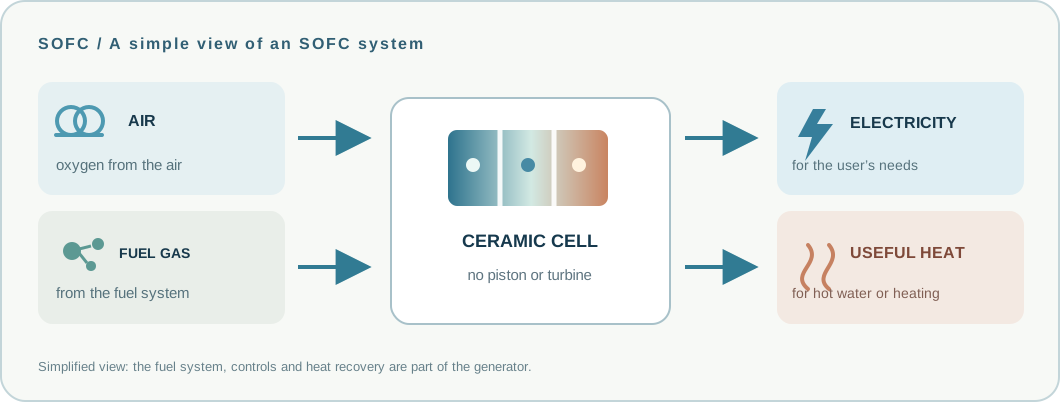
The fuel system delivers what the cells need; its design depends on the fuel for which the generator is configured.
There is no piston in the cell. Electrons move around the external circuit and produce direct current.
The connection method depends on the site and system design. Heat can serve hot water or heating when the project includes heat recovery.
No. The cell continuously needs fuel and air. Generation stops when the fuel supply stops.
Yes, but an individual system is designed for a particular fuel or an agreed set of fuels. The first 1500 W prototype is planned for natural gas; other variants require their own configuration and testing.
Only if the whole system is designed for island operation: controls, bridging storage, protection and reliable fuel supply.
In SOFC, system quality begins long before a generator is assembled. Our programme connects materials science, stack design, fuel processing and controls.
In SOFC, nanotechnology has a practical meaning: work on powder composition, dopants, particles and surfaces affects material properties. As in microelectronics, precise layer architecture matters: porous electrodes, a thin dense electrolyte and functional intermediate layers.
Electron microscopy is one of the key ways to examine material micro- and nanostructure, pores and layer interfaces. Electrochemical measurements show how this architecture performs under load.
Team research on anode structure ↗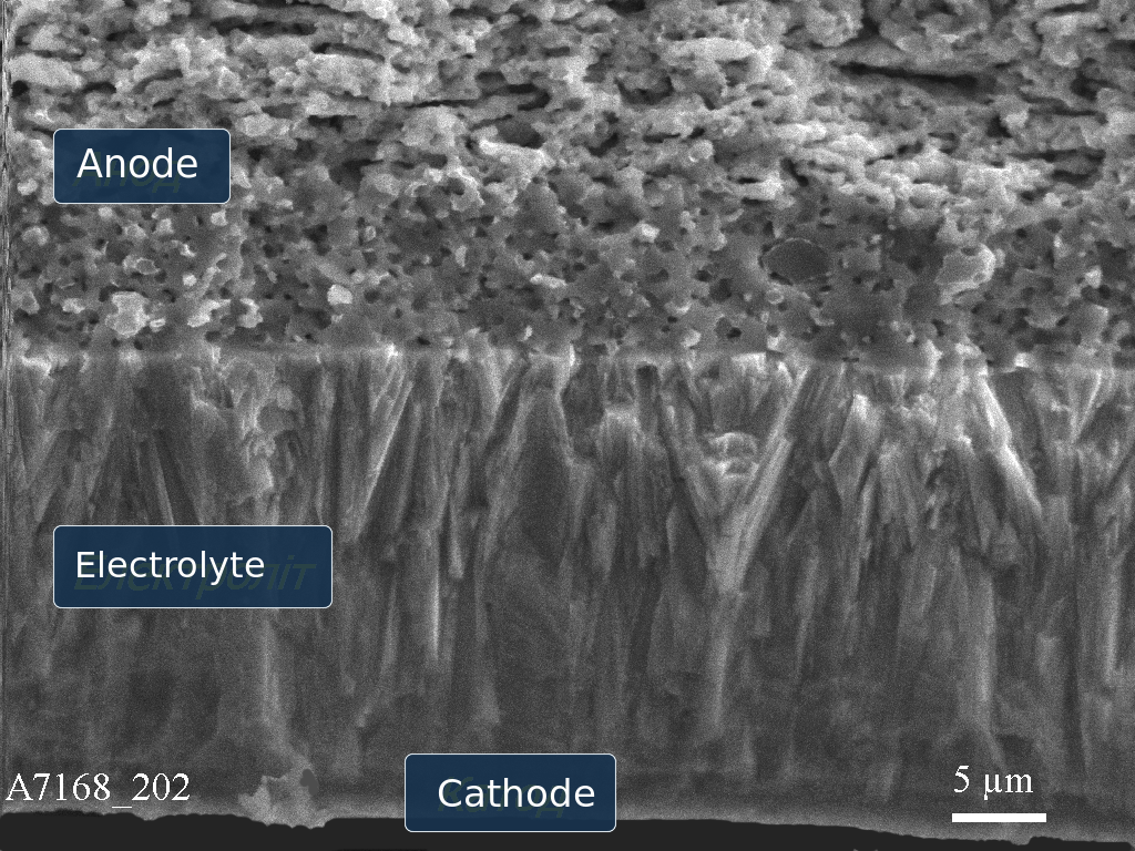
Composition, purity, production process and batch control.
Repeatable performance and process documentation.
Sealing, thermal conditions, replaceability and lifetime.
Fuel system, controls, electronics and heat recovery. The first natural-gas module includes a reformer.
The components and industrial system parameters described here remain subject to development and staged validation.
Scale-up is planned around intermediate technical milestones. Its pace depends on funding, equipment and test results.
Prepare materials, cells, stack design and quality-control protocols.
Stable operation, an external reformer integrated into the module, replaceable stacks and extended durability testing.
Combine them into 50 and 100 kW configurations, validate integration at a partner site and prepare for manufacturing.
Standardised assemblies for systems up to megawatt scale, with cogeneration where appropriate, certification and service.
We welcome conversations with researchers, suppliers of materials and components, industrial partners and investors.